This step-by-step guide will teach you how to establish a Modbus connection between a DCP48M DC-DC converter and a Windows PC using a USB-to-RS485 adapter. By following this tutorial, you’ll learn how to wire the hardware, configure the Modbus communication, and troubleshoot common issues.
Required Material
To complete this tutorial, you’ll need:
- DCP48M (DC-DC converter)
- Windows PC
- USB-to-RS485 adapter (referred to as USB2ModBus-Tool in this guide). For this tutorial we use the Waveshare’s FTDI USB-to RS485 tool. The complete programming kit can also be obtained from DPS. Please contact DPS via the contact form, in the page bottom.
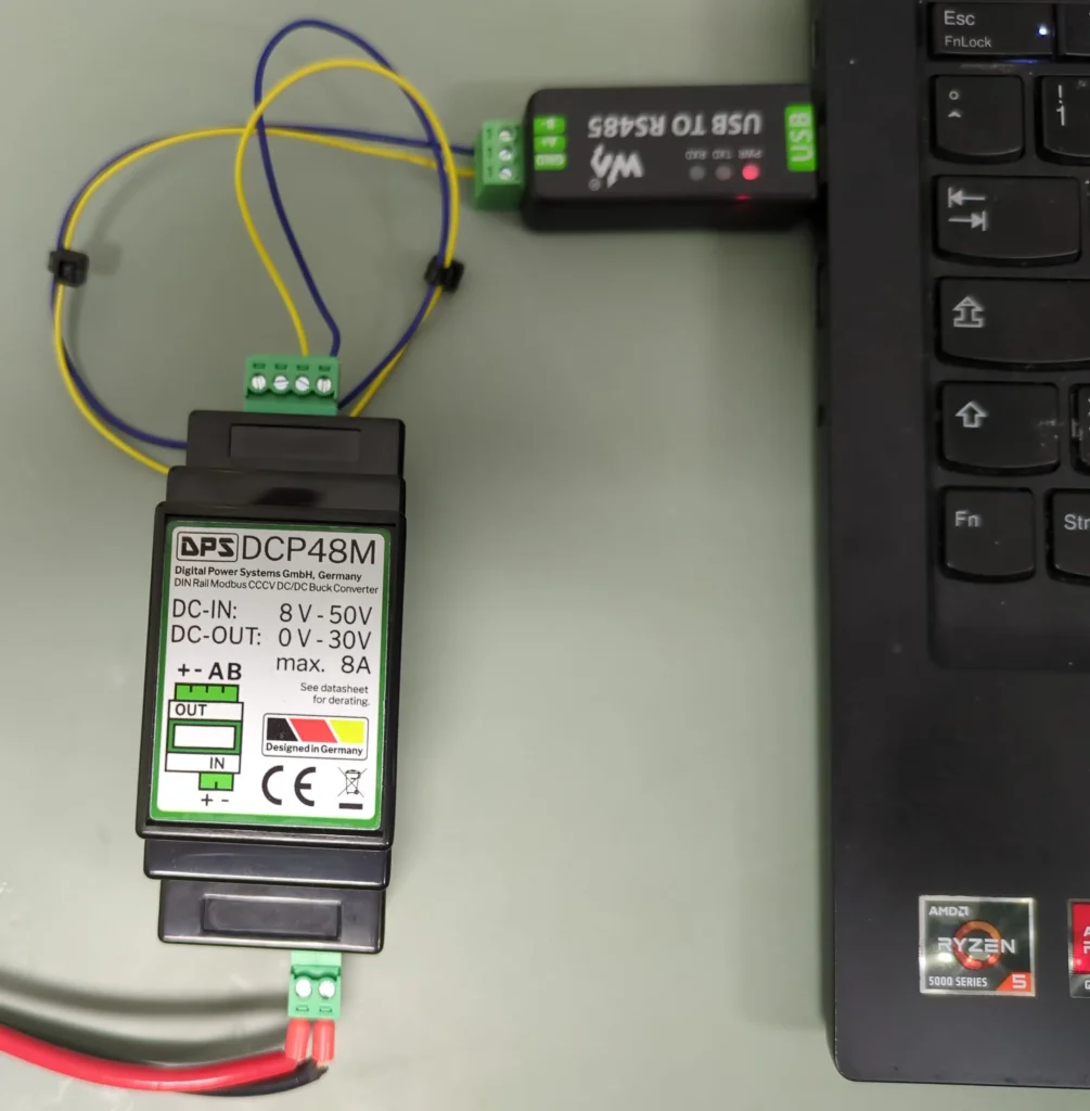
Hardware: Wiring the DCP48M to the USB2ModBus Tool
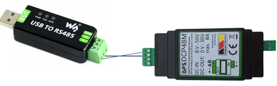
Connecting the hardware is straightforward. Begin by linking the DCP48M to the USB2ModBus-Tool, ensuring that terminal A is connected to A and terminal B to B. Please refer also to the image above.
RS485 communication does not strictly require a ground connection, but if you
prefer to add one, we recommend using the “-” terminal from the power input, which is located on the two-pin connector. Do not use the 4 pin connector, as this might compromise the DCP48M’s current regulation!
Establishing the Modbus Connection PC-DCP48M
To communicate with the DCP48M DC-DC converter via Modbus, we use the Radizio! Modbus Master Simulator (RMMS). This software is available for downloaded from the Digital Power Systems website. Once downloaded, extract the ZIP file to access the executable.
Step 0: Ensure that both your PC and the DCP48M are powered on and that the converter is properly connected to the USB2ModBus-Tool.
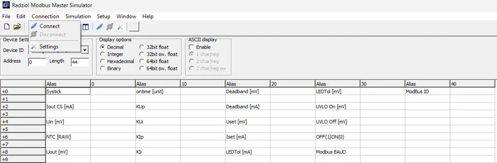
Step 1: Open the downloaded zip, click on RMMS.exe. In the top-dropdown menu.
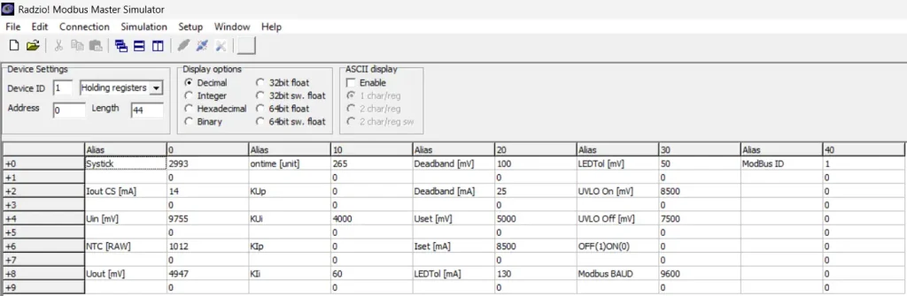
Step 2: Click on the top menu bar File → Open. There you open the configuration file. You will see all loaded configuration data. No data will be displayed.
Step 3: Navigate to Connection → Settings.
Step 4: Ensure that the connection settings are the same as shown in the image below. The PORT has to be the same as the USB2Modbus. Use the device manager (Windows Key-> Device Manager) to determine the COM port.
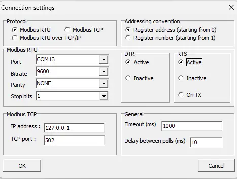
Step 5: Ensure that the connection settings match the recommended values shown in the image below.
Step 6: Click on Connection → Connect. If successful, the DCP48M will connect, and the values will begin updating. The Systick counter should increment by 10 units per second, confirming an active connection.
Beginner’s Questions:
How can I check if the DCP48M has power?
The easiest way to confirm power status is by checking the RGB LED located next to the 4-pin connector on the top of the device. If the LED is illuminated, the unit is powered on. The specific colors and their meanings are detailed in the DCP48M datasheet.
How do I verify if the DCP48M is connected?
In the Modbus software (RMMS), look for the Systick counter at the top of the interface. If the connection is active, this value should increase by 10 every second.
Why are my parameter changes being modified when I want to change the value?
The RMMS software continuously updates data from the DCP48M, which can overwrite manual entries. To securely enter a value:
- Double-click the parameter you want to modify.
- Enter the desired value in the pop-up window.
Which parameters can be updated?
Not all values are modifiable. For instance, Systick cannot be changed. The best way to determine if a parameter is editable is to try modifying it—if the change is accepted, the parameter is adjustable.
How can I permanently save my configuration to the DCP48M?
Once you’ve set all parameters as needed, update either the Modbus ID or the Baud Rate (even if re-entering the same value). This action triggers the device to store all changes permanently.
I accidentally misconfigured the DCP48M and lost the connection. How do I reset it?
If you’ve made changes that prevent communication with the DCP48M, you can restore factory settings:
- Disconnect all loads before proceeding.
- Open the DCP48M’s casing to access the reset switch.
- Press and hold the tactile switch inside the unit.
- The device will revert to its factory default settings, allowing you to re-establish the Modbus connection.
Modifying the DCP48M’s control parameters
⚠ Important: Changing these parameters is a powerful tool but will void any warranty. Proceed with caution.
Basic Parameters
To update a value click on the value. A window will open. There you can enter the desired parameter. Typical parameters that one might want to change:
- Output Voltage (Uset): To change the Output Voltage change USet. Enter the desired value in mV.
- Output Current (Iset): To change the Output Current change ISet. Enter the desired value in mA.
- On(1)Off(0): You can control, if the output is on or off. To turn the converter on, enter a one (1) into this field. To turn it off, enter a zero (0).
Modbus Parameters
The Modbus ID and baud rate of the DCP48M can be reprogrammed. Any changes to these settings will also save all other control parameters.
⚠ After modifying these values, you must reconfigure the RMMS software.
Modbus ID: Sets the Modbus ID of the DCP48M.
- Modbus BAUD: Changes the Boud Rate of the DCP48M.
- Modbus ID: Changes the Modbus ID of the DCP48M.
Control Loop parameters
The DCP48M uses two PI controller for voltage and current regulation. The controller selects the lower of the two control values as the final output.
⚠ Expert Mode Only: Modifying the control loop parameters requires technical expertise. Changes are not saved permanently—to store them, update either the Modbus ID or Baud Rate.
Voltage Control
If you find that the output voltage regulation is not meeting your requirements, you can tune the following parameters.
- KUp: The KUp is the DCP48M voltage PI controllers Proportional (P) gain. Increase the value to have a more responsive control loop, decrease the value to have a more stable and robust control loop.
- KUi: The KUi is the DCP48M voltage PI controllers Integrational (I) gain. Increase the value to have a more responsive control loop, decrease the value to have a more stable and robust control loop.
- Deadband [mV]: The deadband is where the controller does not output any changes to avoid a gittery output. Increase the value to have a more stable control signal, decrease the value to have a more accurate control signal.
Current Control
If you find that the output current regulation is not meeting your requirements, you can tune the following parameters.
- KIp: The KIp is the DCP48M current PI controllers Proportional (P) gain. Increase the value to have a more responsive control loop, decrease the value to have a more stable and robust control loop.
- KIi: The KIi is the DCP48M current PI controllers Integrational (I) gain. Increase the value to have a more responsive control loop, decrease the value to have a more stable and robust control loop.
- Deadband [mA]: The deadband is where the controller does not output any changes to avoid a gittery output. Increase the value to have a more stable control signal, decrease the value to have a more accurate control signal.
I still cannot solve it! Can I get help?
Absolutely, if you use more than 100pcs! Struggling with implementation can be frustrating, but it’s a natural part of the process. No product starts out perfect, and every human makes mistakes—what really matters is learning and improving along the way. Troubleshooting and refining are just steps toward a better solution. Keep going!
Please will out the following support form to get assistance. Please use provide the maximum details to get a fast response. We only support professional project’s